
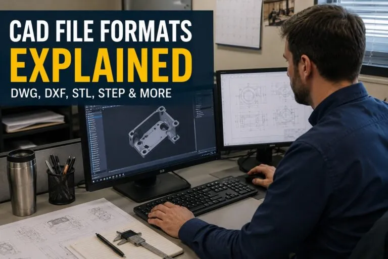
CAD file formats are the foundation of digital design, engineering, manufacturing, and construction workflows. Whether teams are creating mechanical components, architectural plans, electrical schematics, or 3D printed prototypes, choosing the right CAD file format affects collaboration, compatibility, accuracy, and production efficiency.
For hiring managers and HR professionals recruiting CAD designers, drafters, engineers, and technical specialists, understanding common CAD file formats provides valuable insight into the software knowledge and technical skills candidates bring to the workplace. Different industries rely on different formats, and familiarity with multiple file types is often a strong indicator of an experienced CAD professional.
Why Multiple CAD File Formats Exist
No single CAD format serves every purpose. Some formats are designed for editing, while others focus on data exchange, manufacturing, visualization, or long-term archiving.
The file format selected often depends on factors such as:
- The CAD software being used
- Whether files need to be edited or simply viewed
- Manufacturing requirements
- Compatibility with vendors and clients
- 2D versus 3D workflows
- File size and performance
Understanding these differences helps organizations streamline projects and reduce compatibility issues between teams.
DWG
DWG remains one of the most recognized CAD file formats across architecture, engineering, construction, civil engineering, and manufacturing.
Originally developed for AutoCAD, DWG stores both 2D drawings and 3D models while preserving detailed design information.
Common Uses of DWG
- Architectural floor plans
- Mechanical part drawings
- Electrical schematics
- Civil engineering layouts
- Construction documentation
Advantages of DWG
DWG files retain extensive design information, including layers, dimensions, annotations, text, line weights, materials, and metadata. Because the format supports editing, it is commonly used throughout the design process from concept through final revisions.
Many CAD applications now support DWG, making it one of the most widely accepted industry standards.
Limitations
DWG files can become quite large on complex projects. Compatibility between different software versions may also require conversion or updated software.
DXF
DXF, which stands for Drawing Exchange Format, was created to simplify data sharing between different CAD programs.
Unlike DWG, DXF prioritizes interoperability over advanced editing capabilities.
When DXF Is Commonly Used
- Sharing drawings between different CAD platforms
- CNC machining
- Laser cutting
- Plasma cutting
- Waterjet cutting
- Vinyl cutting
Many fabrication shops request DXF files because the geometry can be imported directly into manufacturing equipment.
Benefits of DXF
DXF files are widely supported across CAD applications and manufacturing software. Because they focus primarily on geometry rather than proprietary editing features, they reduce compatibility issues when exchanging drawings between organizations.
Considerations
Some advanced drawing elements, annotations, or custom objects may not transfer perfectly between software applications. Designers often review exported DXF files before sending them to production.
STL
STL has become the standard file format for 3D printing and additive manufacturing.
Unlike engineering CAD files, STL represents only the surface geometry of an object using thousands of interconnected triangles.
Industries That Frequently Use STL
- Product development
- Medical device manufacturing
- Aerospace
- Consumer products
- Education
- Rapid prototyping
Strengths of STL
STL files are lightweight, easy to process, and supported by virtually every 3D printer and slicing application.
They allow manufacturers to quickly prepare models for printing without requiring the original CAD software.
Limitations
STL files do not contain:
- Design history
- Parametric features
- Material information
- Colors
- Dimensions
- Assembly relationships
Because of this, editing an STL file can be significantly more difficult than modifying the original CAD model.
STEP
STEP files are among the most important neutral CAD formats for engineering collaboration.
Officially known as Standard for the Exchange of Product Data, STEP files preserve accurate 3D geometry while remaining compatible across many CAD systems.
Typical Applications
- Mechanical engineering
- Product design
- Supplier collaboration
- Manufacturing
- Assembly design
STEP files are commonly exchanged between companies using different CAD software, allowing manufacturers, suppliers, and customers to work from the same design data.
Advantages
STEP files preserve high-quality geometry while avoiding dependence on a single software platform. They are especially useful when sharing models between SolidWorks, Inventor, CATIA, Siemens NX, Creo, and other engineering applications.
IGES
IGES is another neutral CAD exchange format that continues to appear in many engineering environments.
Although newer standards such as STEP have become more common, IGES remains valuable for legacy projects and older manufacturing systems.
Common Uses
- Legacy engineering projects
- Surface modeling
- CAD data migration
- Older manufacturing equipment
Organizations maintaining long-term product libraries may still receive or archive IGES files as part of ongoing engineering work.
PDF for CAD Drawings
PDF is frequently used to distribute finished engineering drawings without allowing recipients to edit the original design.
While PDF is not an editable CAD format, it plays an important role in documentation and communication.
Typical Uses
- Design reviews
- Customer approvals
- Construction documentation
- Manufacturing instructions
- Vendor communication
PDF drawings preserve formatting and can be viewed without specialized CAD software.
DGN
DGN files are commonly associated with infrastructure and transportation projects.
Widely used with Bentley software products, DGN supports detailed engineering documentation for large-scale public works.
Industries Using DGN
- Transportation engineering
- Highway design
- Rail systems
- Utilities
- Government infrastructure
Some engineering firms regularly convert between DWG and DGN depending on project requirements and client specifications.
OBJ
OBJ files are commonly used when CAD models require visualization rather than engineering edits.
Unlike many engineering-focused formats, OBJ supports texture mapping and color information.
Typical Applications
- Product visualization
- Rendering
- Animation
- Virtual reality
- Marketing assets
Engineering teams often export finished CAD models as OBJ files when working with visualization or graphic design professionals.
Parasolid
Parasolid is a high-precision modeling format used by numerous professional CAD systems.
Many mechanical CAD applications rely on the Parasolid modeling kernel, allowing models to transfer with excellent geometric accuracy.
Common Industries
- Industrial equipment
- Manufacturing
- Automotive
- Aerospace
- Precision engineering
Because Parasolid maintains detailed solid geometry, it is frequently used when exchanging complex mechanical parts.
Native CAD File Formats
Many CAD applications use proprietary file formats that preserve every aspect of the design model.
Examples include:
- SolidWorks (.SLDPRT and .SLDASM)
- Autodesk Inventor (.IPT and .IAM)
- CATIA (.CATPart and .CATProduct)
- Siemens NX (.PRT)
- PTC Creo (.PRT)
Native formats contain complete design history, feature trees, constraints, parameters, and assembly relationships that may not transfer fully into neutral exchange formats.
Choosing the Right CAD File Format
The best format depends on how the design will be used.
| Purpose | Common File Format |
|---|---|
| Editable drafting | DWG |
| CAD software exchange | DXF |
| Cross-platform engineering | STEP |
| Legacy CAD exchange | IGES |
| 3D printing | STL |
| Visualization | OBJ |
| Infrastructure projects | DGN |
| Documentation |
Selecting the correct format reduces unnecessary file conversions and helps preserve important design information throughout a project’s lifecycle.
Common Compatibility Challenges
Even experienced CAD teams encounter issues when exchanging files between software platforms.
Some of the most common challenges include:
- Missing fonts
- Layer mapping differences
- Lost dimensions
- Unsupported features
- Missing materials
- Broken assembly references
- Version incompatibility
- Unit conversion errors
Many organizations establish internal CAD standards that specify acceptable file formats for internal work, customer deliverables, and manufacturing partners.
CAD File Formats and Hiring Considerations
For hiring managers recruiting CAD professionals, file format knowledge often reflects broader technical experience.
Candidates who have worked across multiple CAD platforms are typically familiar with exchanging files between software packages while maintaining design integrity.
Interview discussions may include experience with:
- Exporting manufacturing-ready files
- Preparing files for CNC machining
- Creating models for 3D printing
- Converting between native and neutral formats
- Resolving compatibility issues
- Working with suppliers using different CAD software
- Managing revision control across multiple file types
Experience with several CAD file formats often indicates that a candidate has collaborated across departments, vendors, and engineering teams rather than working exclusively within a single software environment.
CAD file formats influence nearly every stage of product development, engineering, architecture, manufacturing, and construction. From DWG and DXF for drafting to STEP for engineering collaboration and STL for additive manufacturing, each format serves a specific purpose within the design process. Understanding these formats helps organizations improve collaboration, reduce compatibility issues, and identify CAD professionals with the technical expertise needed to support efficient project execution.
Content reviewed and published by Tier2Tek Staffing Editorial Team.